Tristate Machinery Dismantlers Forum > ILLINOIS
> Electrical Components
> New
> Without Warranty
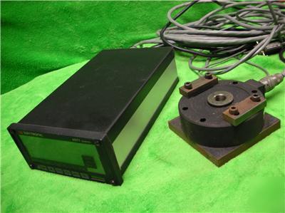
> Daytronic cell 3173-100 dc strain gage transducer 4077
Daytronic cell 3173-100 dc strain gage transducer 4077
DAYTRONIC CELL 3173-100 DC STRAIN GAGE TRANSDUCER 4077
from http:// /Products/4K/4kDCstrain.htm :
The single-channel Model 4077 is a versatile general-purpose instrument for input of pressure, force, torque, weight, and other variables measured by DC-excited strain gage transducers.
Unlike the other 4000 Series "Standard Input Models," the 4077 provides two special analog channels for real-time capture of both positive and negative peak input values. (ALL 4000 instruments are capable of digital peak capture, via special "MAX" and "MIN" data channels. The validity of digitally captured peak values is necessarily limited, however, by the scan rate of the instrument's Central Processor. This is not the case with the 4077's purely analog peak-capture capability, which yields true real-time maxima and minima, regardless of the current scan rate.)
The 4077 accepts a single input from any DC-excited load cell, pressure sensor, or other conventional 4-arm strain gage bridge, nominal 120 or higher, with a full-scale range of 1.5 or 3.0 mV/V. Optional bridge-completion circuitry is provided by the Model 10CJB-2, allowing input from a 2-wire 1/4-bridge, 3-wire 1/4 bridge, or 1/2-bridge gage configuration, as shown in Stress Analysis Using External Bridge Completion.
Advanced circuit design overcomes many of the errors traditionally afflicting the strain gage measurement process, resulting in rock-solid digital indication and noise-free analog output.
Other important 4077 features include
selectable bridge excitation (nominal 5 or 10 VDC)
remote sensing and regulation of bridge excitation eliminates errors from temperature effects on cable resistance and yields consistently stable ratiometric measurement, unaffected by possible power-supply drift
input impedance in excess of 100 megohms preserves the validity of factory calibration, prevents conversion of common-mode to normal-mode signals, and eliminates remaining errors attributable to cable resistance. Allowable cable length has virtually no practical limits.
As with most standard 4000 Series models, both active low-pass filtering and user-selectable digital smoothing eliminate dynamic components arising from vibration, power impulses, etc., that might prevent stable digital conversion or control action (see Specifications).
The 4077's "+PEAK" channel detects and stores in capacitor memory the most positive value experienced by the input since it was last reset by an appropriate "+PEAK TRACK" command. The "-PEAK" channel detects and stores the most negative value since the last "-PEAK TRACK" command. Commands to control peak-capture operation may be issued via the Interface Port, by an optional Model 10P80D Extended Keyboard, or by TTL-level logic inputs received at the 4077's rear-panel I/O Connector.
Each peak value will remain in memory until reapplication of the respective "TRACK" command, or until occurrence of a subsequent more positive or more negative signal excursion (thus permitting the capture of successively higher maxima or successively lower minima). The following diagrams show the different possible modes of real-time peak capture (and reset); see the Model 4077 Instrument Instruction Manual for complete details.
Capture and Hold of Successively Higher-Valued Maxima
Capture and Hold of Successively Lower-Valued Minima
Capture and Hold of Successively Lower-Valued Maxima
Using "Reset" of "+PEAK" Channel
Capture and Hold of Successively Higher-Valued Minima
Using "Reset" of "-PEAK" Channel
The 4077's capacitor memory is volatile, and entails inevitable decay of captured signal values. The actual decay rate does not exceed 0.4% of full scale/second (e.g., with full scale of 20000 counts, it will not exceed 8 counts/100 msec). The decay rate is small enough to allow essentially perfect capture and indefinite (digital) hold of signal peaks, using the special digital "MAX" and "MIN" channels, as shown in the following diagram.
Use of "MAX" Calculate Channel for
Nonvolatile Holding of Captured "+PEAK"
For a 4077-based instrument specifically dedicated to the detection, display, and evaluation of real-time peaks in all kinds of industrial applications and offering a special "peak trend modification" see the Model 4K/PM-77 Peak Monitor.
Simple two-point "zero and span" calibration is provided for the 4077's input channel. In addition, a 100-k , 0.1% shunt resistor is supplied. You can use this resistor or one or your own to apply an "equivalent input" for calibration purposes, when the transducer's full-scale mV/V sensitivity is accurately known. The calibration shunt may be switched in and out for either a positive or negative up-scale reading by simple mnemonic commands issued via the Interface Port or optional Model 10P80D Extended Keyboard.
A third calibration technique for the 4077 involves application of a special MILLIVOLT/VOLT CALIBRATION (MVV) command through the Interface Port or optional keyboard when both "mV/V" sensitivity and corresponding full-scale rating of the transducer are known.
MODEL 4077 "STANDARD CONFIGURATION"
(for a complete listing of the configuration, click here)
A preprogrammed tare function may be activated by front-panel button
Channel Nos. 2 and 3 are "ANALOG +PEAK" and "ANALOG -PEAK" of the "live" input channel (respectively)
Via front-panel buttons, you can call to display the "live" tared input; the digitally captured maximum (most positive) value of that input since last reset; the digitally captured minimum (least positive) value of that input since last reset; or the existing net difference between these digital maximum and minimum values
The digital "MAX" and "MIN" functions can be reset by a front-panel button
Each of the standard seven predefined limit zones of the tared input reading is tied to a specific nonlatching logic output
The 4077's 10 VDC analog output derives from the tared analog input, and is initially scaled for 1 mV of output per count
For typical 4077 operations, see the following applications:
Measuring Amount of Conveyed Material (in conjunction with the Model 4040 Frequency Instrument)
Flow Measurement Derived from Pressure Drop Across an Orifice
Measuring Valve Opening Pressure
Leak Testing of Hydraulic Hoses
Stress Analysis Using External Bridge Completion
4000 Series options applying to the Model 4077 include
RS485 (network) data communications
DC-powered (vehicle) operation
DC Strain Gage Instrument Specifications [Top ](Click here for 4000 Series General Specifications; see also
the statement on Daytronic accuracy specifications)
Conventional 4-arm strain gage bridge, nominal 120 or higher
NOTE: 1/4- and 1/2-bridge gage configurations can be accomplished by means of the Model 10CJB-2 Bridge Completion Card, or by equivalent external bridge completion circuitry supplied by the user.
Selectable 5 or 10 VDC, nominal; 80 mA maximum
50 mV peak operating; 8 V without instrument damage
0.25 V peak operating; 8 V without instrument damage
-90 dB at DC; -120 dB at 60 Hz, 1 kHz, and 3 kHz
Input Impedance (Differential and Common-Mode)
0.02% of full scale 1 count LSD, typical, following calibration**
Does not exceed 0.4% of full scale/second (e.g., with full scale of 20000 counts, decay rate will not exceed 8 counts/100 msec)
3-pole modified Butterworth; -3 dB at 20 Hz; -60 dB at 220 Hz
Step Response Settling Time (Full-Scale Output)
To 0.02% of final value: 125 ms
* Since channel zeroing is by digital techniques, no input balance control is provided. The allowable input range, therefore, must include an initial unbalance (which, in commercially produced strain gage transducers, is negligible). Other transducers may have to be externally trimmed to be used with the Model 4077, if zero unbalance exceeds 20% of full scale.
** Initial (uncalibrated) inaccuracy may be as great as 0.05% of full scale. Maximum error that could occur upon replacement of the Model 4077 not followed by calibration is 0.1% of full scale.